High speed data transmission method for Arduino nano 33 ble
1. Tested flip pin speed of Arduino nano 33 BLE Sense
Code: while(1){
digitalWrite(A0,HIGH);
digitalWrite(A0,LOW);
}
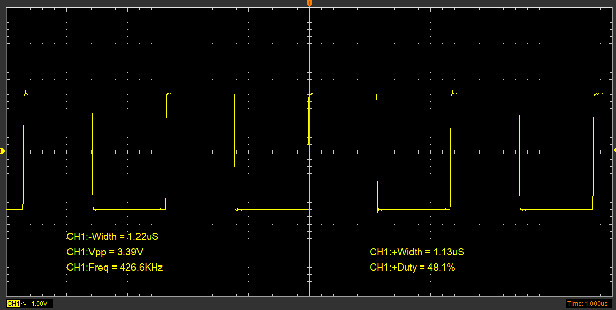
Figure 1. approx. 426 kHz
Why so slow: Control by mbed-OS
2. Tested SPI error at very low speed
34 became 68:
34: 0010 0010
68: 0100 0100
Problem: clock did not align.
3. Develop corrected SPI and test its speed
FAILED: With more than 75% error transmission, it will cost at least 4 times.
Risk Evaluation:
Continuing SPI development by directly setting registers will face two risks:
- It may take many days, even weeks, to learn and debug the low-level driver for Arduino-nRF register development due to the lack of documents.
- There is still a risk of the not aligned clock problem. (might make many efforts in vain)
4. Direct operate register
NRF_P0->DIRSET = 0xFF; //P0 lower 8bit = Input Mode
while(1){
NRF_P0->OUTSET = 0xFF; //P0 lower 8bit = Output High
NRF_P0->OUTCLR = 0xFF; //P0 lower 8bit = Output Low
}

Figure 2. Approx. 12.76MHz (Probe x10)
Even faster while using 32bits hex:
uint32_t PortD[] = {0x00000800,0x00001000}; //D2,D3
while(1){
NRF_P1->OUTSET = PortD[1];
NRF_P1->OUTCLR = PortD[1];
}

while(1){
NRF_P0->OUTSET = 0xFF; //P0 lower 8bit = Output High
NRF_P0->OUTSET = 0xFF;
NRF_P0->OUTSET = 0xFF;
NRF_P0->OUTSET = 0xFF;
NRF_P0->OUTSET = 0xFF;
NRF_P0->OUTCLR = 0xFF; //P0 lower 8bit = Output Low
NRF_P0->OUTCLR = 0xFF;
NRF_P0->OUTCLR = 0xFF;
NRF_P0->OUTCLR = 0xFF;
NRF_P0->OUTCLR = 0xFF;
}
Conclusion: Directly operating the register can unleash the capabilities of the nRF52840. Due to the limitations of my oscilloscope, I cannot confirm if it reaches the specifications detailed in the nRF52840 datasheet.
5. Compare Speed
while(1){
NRF_P0->OUTSET |= PortA[0]|PortA[1]|PortA[2]|PortA[3]|PortA[4]|PortA[5]|PortA[6]|PortA[7];
NRF_P0->OUTCLR |= PortA[0]|PortA[1]|PortA[2]|PortA[3]|PortA[4]|PortA[5]|PortA[6]|PortA[7];
}
Result: Shifting between 4.96MHz & 6.44MHz
while(1){
for(int i=0; i<8; i++){
NRF_P0->OUTSET |= PortA[i];
}
for(int i=0; i<8; i++){
NRF_P0->OUTCLR |= PortA[i];
}
}
Result: Approx. 353kHz
while(1){
NRF_P0->OUTSET |= PortA[0];
NRF_P0->OUTSET |= PortA[1];
NRF_P0->OUTSET |= PortA[2];
NRF_P0->OUTSET |= PortA[3];
NRF_P0->OUTSET |= PortA[4];
NRF_P0->OUTSET |= PortA[5];
NRF_P0->OUTSET |= PortA[6];
NRF_P0->OUTSET |= PortA[7];
NRF_P0->OUTCLR |= PortA[0];
NRF_P0->OUTCLR |= PortA[1];
NRF_P0->OUTCLR |= PortA[2];
NRF_P0->OUTCLR |= PortA[3];
NRF_P0->OUTCLR |= PortA[4];
NRF_P0->OUTCLR |= PortA[5];
NRF_P0->OUTCLR |= PortA[6];
NRF_P0->OUTCLR |= PortA[7];
}
Result: Approx. 976kHz
5. Develop pallallel protocol
The IO set address is unknow and there is no information online.
The solution is to use the Arduino function:
pinMode(A1, INPUT);
And read using register:
Serial.println(NRF_P0->IN);
Basic idea:
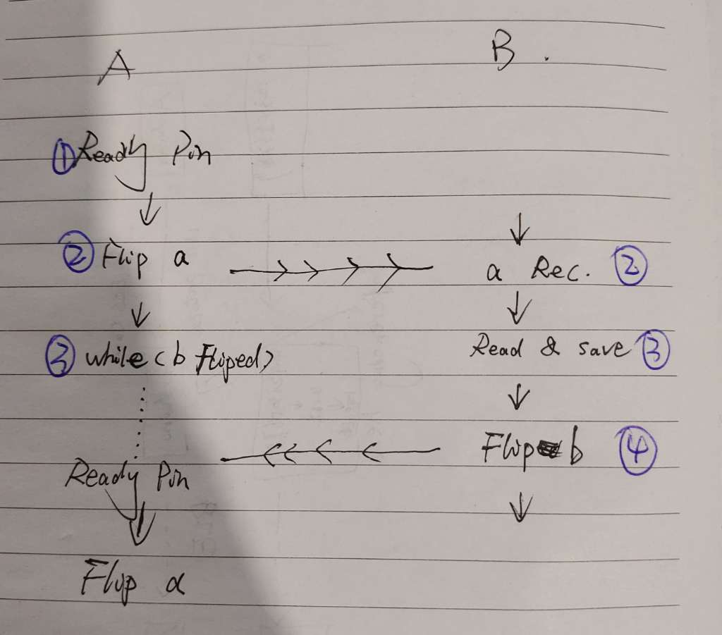
Figure 5. The logic of communication between Machine A & Machine B
Logic:
Machine A - Step 1: Set Data Pins
Machine A - Step 2: Flip trigger-a
Machine A - Step 3: Wait() for b being flipped
Machine B - Step 2: Received a
Machine B - Step 3: Read & Save Data
Machine B - Step 4: Flip trigger-b
(Go to another loop)
This method is for the fastest transmission and confirmed reception.
Coding Design:
KEY Optimazation Method for acceration:
- Table-based method: To calculate data in a batch and save to a array, while using it to the port, direct extract the element from the array.
- Use XOR replace if()function to acceration: NRF_P1->OUT ^= PortD[1];
- Use union
Comparison:
Comments
Post a Comment